TV Distortion vs. Optical Distortion: How Exactly Do You Convert Between Them?
 11/09 2026
 482
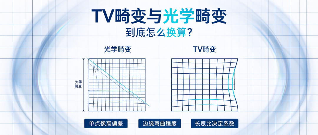
Abstract: Optical distortion describes the image height deviation of a single point, whereas TV distortion measures the degree of curvature at the image edge.
There is no fixed 1/3 conversion coefficient between the two; the coefficient is determined by the sensor aspect ratio—approximately 0.32x for 4:3 and approximately 0.38x for 16:9.
In optical design and image quality evaluation, one must first distinguish between the definitions of these two metrics before attempting any conversion.
Those working in optical design have most likely run into this confusion: Zemax simulation reports an optical distortion of -30%, yet the customer's test report shows a TV distortion of only 11%.
The two numbers differ so dramatically—which one is correct? The answer is that neither is wrong. They describe two different dimensions of distortion: optical distortion reflects how much a single point shifts, while TV distortion reflects how much the image edge bends.
Optical Distortion — The "Position Deviation" of a Single Point
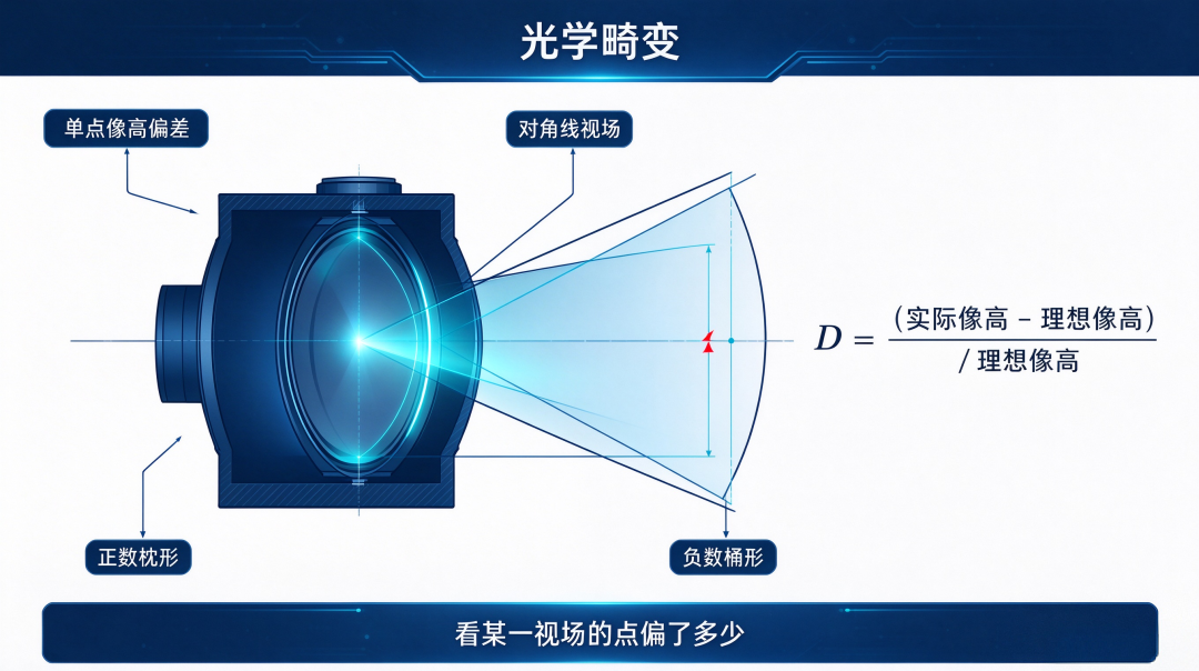
The definition of optical distortion is straightforward: take the image height at the actual imaging position, subtract the image height under ideal conditions, divide by the ideal image height, and convert the result to a percentage.
The ideal image height is calculated from the focal length and field angle: Ref.H = f × tan(θ). The actual image height comes from simulated ray tracing or physical testing. Dividing the difference between the two by the ideal image height yields the optical distortion. Optical distortion is generally taken as the value at the maximum diagonal field of view.
A positive value indicates pincushion distortion, where the image edge stretches outward; a negative value indicates barrel distortion, where the image edge contracts inward. This metric reflects the position error of a single imaging point and tells you how far light at a given angle deviates during imaging—but it cannot directly show whether the image appears bent.
TV Distortion — The "Degree of Curvature" at the Edge
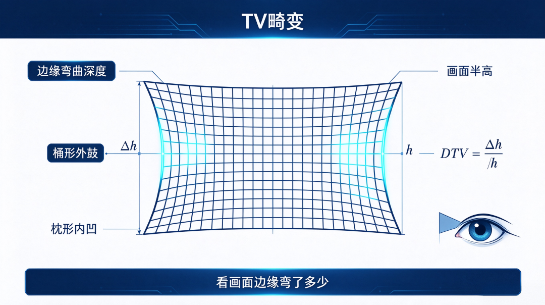
The evaluation logic behind TV distortion is entirely different. It does not focus on individual pixel points but specifically measures the degree of curvature at the image edge.
Standard definition: the bending depth Δh at the image edge divided by the half-height h of the image, multiplied by 100%. Picture a standard rectangular grid pattern: barrel distortion makes the four sides of the rectangle bulge outward; pincushion distortion makes them cave inward.
TV distortion quantifies the ratio of this bulging or cave-in relative to the image half-height. TV distortion aligns more closely with intuitive human perception.
When we look at an image, we do not calculate the coordinate offset of each pixel one by one—yet we can spot at a glance whether the image edge is bent. This is precisely why the television and display industries commonly use TV distortion to evaluate image quality.
Conversion Relationship — Why Isn't It a Fixed "1/3"?
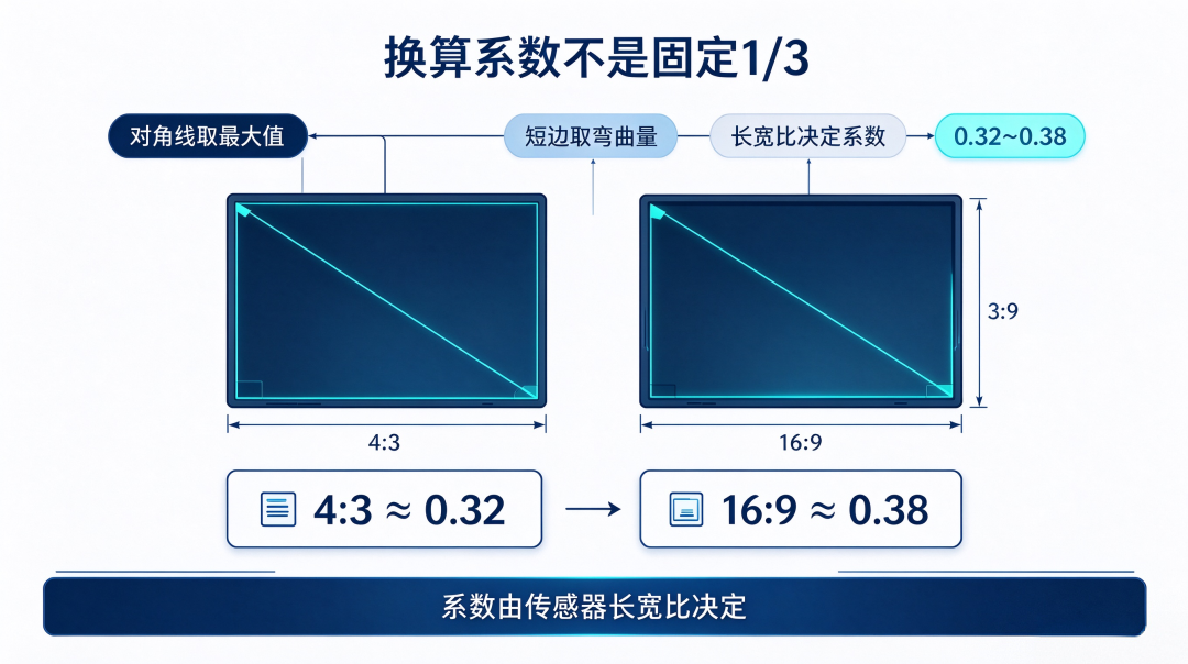
There has long been a rule of thumb in the industry: TV distortion is approximately equal to 1/3 of optical distortion. This estimate can serve only as a rough reference; it is not a rigorous engineering formula. The conversion coefficient is determined by the sensor aspect ratio.
The underlying reason is that optical distortion takes the maximum value at the diagonal field of view, while TV distortion takes the bending amount in the short-side direction. The conversion coefficient is therefore a function of the geometric ratio between the diagonal and the short side. For a 4:3 sensor (typically a 1/3-inch image sensor): DTV ≈ 0.32 × D.
Example: -30% optical distortion corresponds to a TV distortion of approximately -9.6%. For a 16:9 sensor (typically a 1080P chip): DTV ≈ 0.38 × D. Example: -30% optical distortion corresponds to a TV distortion of approximately -11.4%. The conversion coefficient fluctuates between 0.32 and 0.38, determined by the chip aspect ratio.
1/3 is merely an approximation for easy memorization; for formal engineering calculations, the corresponding precise coefficient must be used.
A Specific Conversion Example. Let's take measured data from a thermal imaging lens as an example: optical distortion of -90% with a 4:3 sensor—an extreme case of an ultra-wide-angle/fisheye large-field-of-view thermal imaging lens.
Conversion approach: first obtain the image half-height h in the short-side direction, find the ideal image height Ref.H1 corresponding to the short side, use the aspect ratio to derive the theoretical ideal image height Ref.H0 at the corner, read the actual image height Real.H0 at the corner, and calculate the post-distortion corner height h0.
The final calculation gives a TV distortion of DTV = (h - h0) / 2h ≈ 11.2%. An optical distortion of -90% converts to a TV distortion of only about 11.2%.
This huge discrepancy shows that although the optical distortion value looks alarming, once converted to TV distortion, the image deformation perceived by the human eye is far milder—yet both describe the same distortion phenomenon.
Implications for AR Optical Waveguide Design
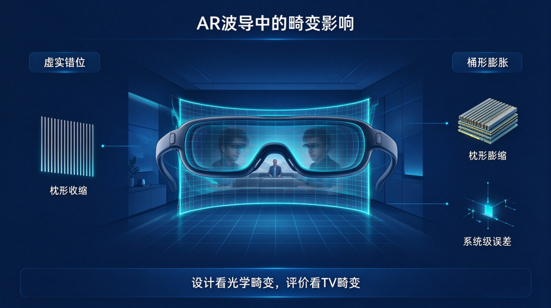
In AR optical waveguide scenarios, distortion directly determines whether the virtual image and the real world can be accurately overlaid and aligned.
If the waveguide introduces barrel distortion, the edge of the virtual image will expand outward and misalign with real objects; pincushion distortion will cause the image edge to contract inward.
Common engineering practice: use optical distortion as the optimization target during the design phase, and refer to TV distortion for final acceptance evaluation—because what users perceive with their naked eyes is TV distortion, not the optical distortion output by simulation software.
AR glasses have extremely high requirements for virtual-real overlay accuracy, generally needing to be controlled within a few pixels, so distortion must be precisely managed.
The sources of AR optical waveguide distortion are not limited to grating diffraction; multilayer waveguide stacking deviations and optical engine assembly errors also introduce distortion.
System distortion is the combined result of optical design, material processes, and assembly precision. Conclusion: Optical distortion reflects how much a single point shifts; TV distortion reflects how much the image edge bends.
There is no fixed 1/3 for conversion between the two; the coefficient falls between 0.32 and 0.38, depending on the sensor aspect ratio. Only by distinguishing the physical meanings of these two metrics and thoroughly understanding the conversion logic can one accurately assess the true image quality level of an optical system.
Discussion topic: In your optical design work, are you more accustomed to using optical distortion or TV distortion when evaluating distortion? Have you encountered problems with mismatched conversion coefficients? Feel free to leave a comment and share your experience.
[Risk Note] This article is a popular science piece on optical engineering; the conversion formulas herein are derived based on an ideal geometric model. Actual lenses will exhibit coupling effects such as astigmatism and field curvature, and sensor pixel layouts and testing algorithms will also introduce minor deviations. Final distortion values are subject to actual measurements of the complete device.
—— AR Andy | Focused on the optical waveguide and AR micro-display track, providing in-depth analysis of the underlying logic of the optical industry
-
![]()
Valuation in the Hundreds of Billions, Revenue Just Over a Billion—Can Kling AI Carry Kuaishou's Second Growth Dream?
-
Alibaba Cloud Token Plan Boosts Quota by 70% Starting Today
-
![]()
Just the Facts, No Emotions—Has AI Actually Crashed or Not?
-
![]()
New Forces' Annual Targets in Jeopardy?
-
![]()
In 2026, Tencent Is Frantically Playing Catch-Up
-
![]()
Optical Brain-Computer Interface Paves the Way for Chip Integration! Huichuang Medical Makes Strategic Investment in Westlake Neuralicorn
-
![]()
First Three Quarters Non-Recurring Profit Jumps 116.94%! Why Is Wavelength Optoelectronics Betting Another 150 Million?
-
![]()
TV Distortion vs. Optical Distortion: How Exactly Do You Convert Between Them?