Design Verification of Auto Parts Using Traditional Methods: How Traditional Automakers Develop, Verify, and Release a 'Brake Pedal'
 10/10 2026
 368
368
The recent incident of a brake pedal breaking underfoot has gone viral. Many have flocked to the Vehicle platform to ask Jack for interpretation and commentary on the matter. To be honest, it's hard to comment on.
However, we can still provide interpretation and education, though these traditional methods are rarely seen nowadays.
After some thought, I decided to sift through a batch of engineering documents stored on my hard drive.
These documents are from two joint venture vehicle projects of a multinational automaker in the 2010s, referred to as Project A and Project B hereafter. They include product development processes, design verification records, corporate testing standards, and several internal procedures.
After reviewing them, my biggest takeaway is that it takes over three years for a pedal to go from the first digital mock-up to approval for mass production, passing dozens of engineering requirements and requiring multiple rounds of signatures.
This article will not comment on the recent brake pedal breaking incident but will instead clarify the traditional methods used by automakers to design, verify, and release a brake pedal. Perhaps you'll find answers here.
Note: To avoid any potential issues, I have replaced the system names and official numbers in the documents with functional names and illustrative numbers (such as R-01, P-01, S-01), maintaining only the correspondence without allowing for the retrieval of official documents.
Let's dive right in.
01 Breaking Down a Pedal: It's an Interface Component, with Challenges at the Boundaries
In engineering terms, a 'brake pedal' is actually an assembly.
Pedal arm and tread
Pivot shaft, bushing, and return spring
Pedal bracket mounted on the dashboard panel
Pin connecting to the vacuum booster pushrod
Brake light switch detecting pedal movement
For manual transmission models, the clutch pedal may also be mounted on the same bracket. In Project A's verification records, the clutch and brake pedals are treated as a single module.
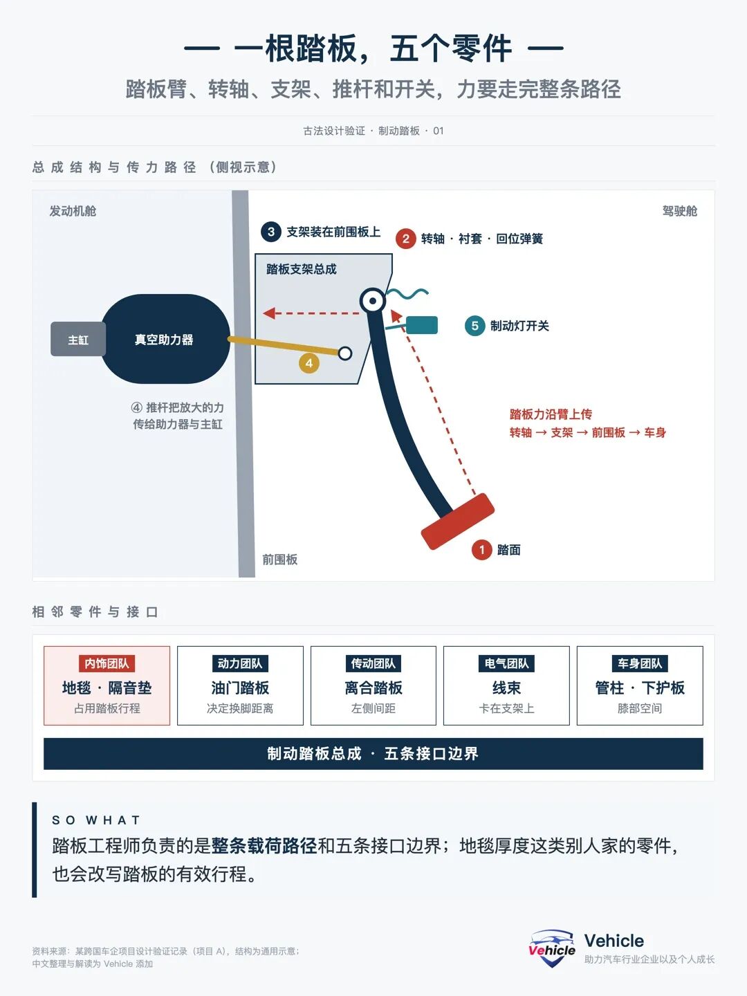
When the foot presses down, force is transmitted along the pedal arm to the pivot shaft, then through the bracket to the dashboard panel and vehicle body. Simultaneously, the pushrod sends amplified force into the booster and master cylinder.
Weak links in the force transmission chain—welds, holes, bushings, fasteners, bracket bases—are prone to failure first.
Thus, my understanding is that pedal engineers are responsible not just for the arm but for the entire load path.
Another easily overlooked aspect: interfaces.
Carpet and sound insulation pads can reduce pedal travel, the accelerator pedal determines foot transfer distance, the clutch pedal restricts left-side spacing, wiring harnesses must be secured on the bracket, and the steering column and lower shroud determine knee space.
The recent brake pedal breaking incident involved a fracture between the pedal arm and bracket.
Project A includes a requirement for pedal travel, ultimately assigned to the interior team. The reason is simple: thicker carpets shorten the effective pedal travel.
The design boundaries of a pedal extend to components from other teams.
02 Requirements Precede Drawings: Qualification Standards Are Set Before Pen Hits Paper
Many assume engineers design based on experience.
Not in this system. Before design begins, applicable engineering requirements are already assigned to specific components.
The process goes like this: corporate standards contain all requirements, which the design verification system distributes to projects. Projects then filter out relevant items and apply them to the brake pedal assembly.
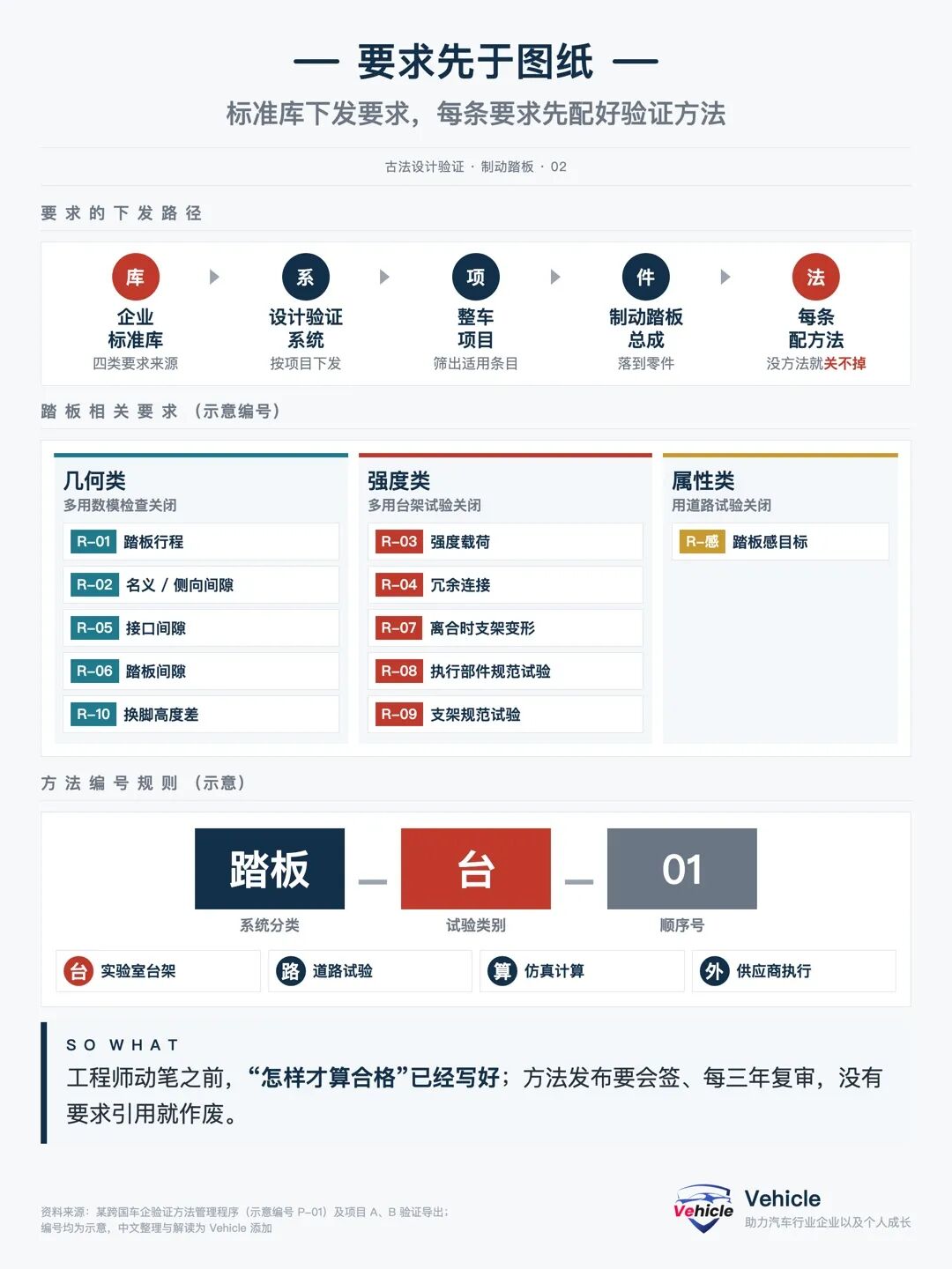
Requirements come from four categories: regulatory, corporate general, competitiveness or gap, and component specifications.
For brake pedals, I've compiled a list (illustrative numbers):
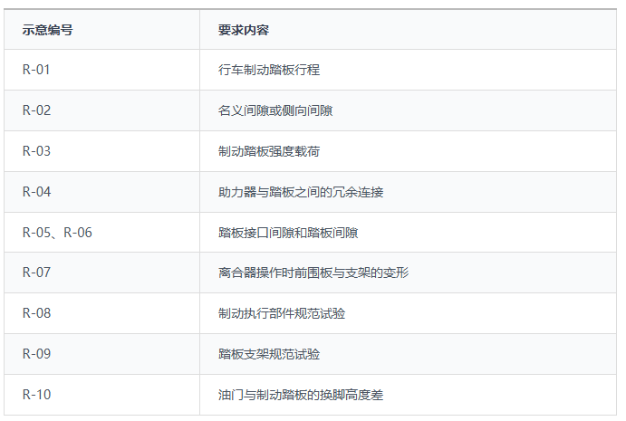
Three requirements stand out as particularly engineering-focused.
R-04, titled BRAKE PEDAL PROOF LOAD, involves applying a specified overload to the brake pedal assembly to demonstrate that the pedal arm, pivot shaft, bracket, and body connection points remain intact under this force. It proves structural integrity, not pushing the component to failure—key to the recent pedal breaking incident.
Normal driver braking force and regulatory test forces range from 65 to 500 N. The proof load exceeds these daily and certification forces, applied to the pedal pad in the pressing direction; some standards also include lateral forces (remember lateral forces, as they may have played a role in the recent incident). After applying the force for several seconds, it is released, and the following are checked:
No cracks, buckling, weld fractures, or connection looseness
Permanent deformation does not exceed limits
Pedal returns to its original position after force release, and braking function remains
Passing only indicates it withstood the proof load. The force required to cause failure is the ultimate load, which is tested in another trial. The standards here are corporate, varying by company.
R-04 also requires redundant connections between the booster and pedal. If one connection fails, a backup structure must transmit braking force.
R-07 monitors deformation of the bracket and dashboard panel during clutch engagement. Frequent clutch use can deform the bracket, potentially affecting the adjacent brake pedal.
01 Every Requirement Needs a Verification Method
This is a fundamental rule of the system: requirements without verification methods cannot be closed in the system.
Methods have their own numbering system: system classification + test category + sequence number. Test categories include bench, road, simulation, and supplier external testing.
Methods must be co-signed by the requesting department and the testing department before release and are reviewed at least every three years. Methods no longer referenced by any requirement are invalidated.
If you're involved in component development, this comparison card can be used directly, with one requirement per row and empty cells indicating areas needing clarification.
Requirement-Verification Method Comparison Card (Directly Copyable)
Requirement Number:
Requirement Content:
Requirement Category: Regulatory / Corporate General / Competitiveness / Component Specification
Verification Method: Digital Mock-up Check / Computational Simulation / Bench Test / Road Test / Supplier Test
Acceptance Criteria:
Sample Status: Digital Mock-up / Prototype / Tooling Sample / Mass Production Part
Planned Completion Milestone:
Responsible Person:
Current Status: Completed / On Schedule / Conditional / No Plan / Not Applicable
When engineers begin drawing, 'what qualifies as acceptable' is usually already defined.
03 Three Rounds of Digital Mock-ups Approach Mass Production: Solving Issues in Digital Mock-ups Is Cheapest
The development process divides underbody component design into three rounds, referred to here as D0, D1, and D2, followed by mass production data release.
Time is measured in 'weeks until mass production data release.' The weeks below are illustrative windows, showing only the duration of each phase.
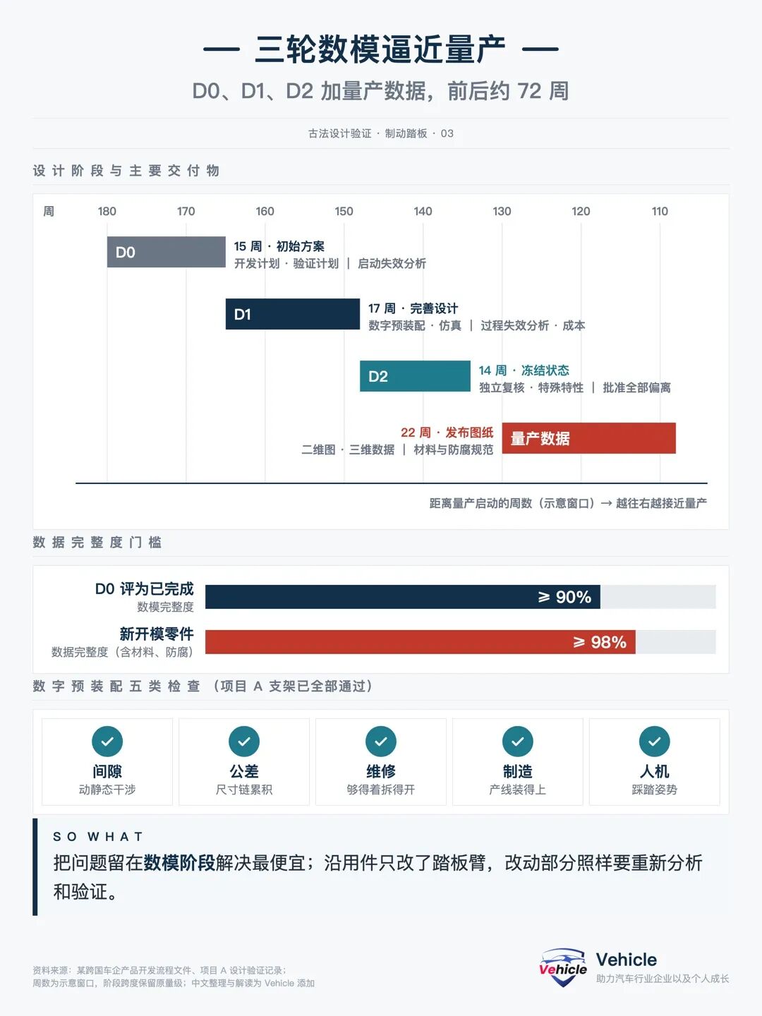
STEP 01 D0: Develop a Feasible Solution (Approx. 15 Weeks)
Determine mechanical layout based on platform selection and carry-over component data. Tasks include collecting historical quality issues and competitor benchmarks, compiling a component development plan, drafting a design verification plan, initiating design failure analysis, creating the D0 digital mock-up and bill of materials.
The component development plan is the master schedule for the pedal, aligning vehicle milestones, pre-assembly, failure analysis, testing, prototyping, and tooling cycles on a single timeline. The goal is straightforward: avoid discovering too late that tooling or testing cannot meet deadlines after designs are finalized.
D0 concludes with an approval meeting, considering the digital mock-up over 90% complete as finished.
STEP 02 D1: Refine the Component (Approx. 17 Weeks)
Modify the component based on digital pre-assembly and simulation results, document failure modes and countermeasures in failure analysis, conduct process failure analysis with manufacturing, and hold a cost review meeting.
Digital pre-assembly involves 'assembling the vehicle' virtually with the digital mock-up to check five types of issues: clearance, tolerance, serviceability, manufacturability, and ergonomics. Project A's records indicate that the pedal bracket's digital mock-up passed all five checks.
STEP 03 D2: Confirm and Freeze (Approx. 14 Weeks)
Complete verification of new technology prototypes, have an independent review conducted by someone not involved in the design, define special and critical characteristics, and approve all design deviations.
Subsequently, release 2D drawings, 3D data, and material specifications in mass production status over approximately 22 weeks. Data completeness for newly tooled components must reach over 98%.
02 Carry-over Components Are Not Exempt
Project A's Chinese version carried over the European pedal bracket, modifying only the brake pedal arm.
While carry-over components save on verification workload, modified sections still require re-analysis and re-verification. A 'change point' method in failure analysis is used to monitor these modifications.
Identifying one more issue during the digital mock-up phase reduces tooling rework later.
04 Proving Qualification Through Three Methods: Digital Mock-up, Bench, and Road Tests, Each Covering a Phase
The design verification plan and report are the primary documents for component verification. Verification methods fall into three categories.
01 Digital Mock-up and Computation
Clearance, travel, envelope, and ergonomic dimensions are typically verified during the digital mock-up phase without waiting for physical prototypes. Project B's foot transfer height difference (R-10) was closed using a digital mock-up-based compliance check.
02 Bench Testing
Strength loading (R-03) and bracket specification tests (R-09) are conducted on benches, focusing on three aspects: whether cracking occurs, the extent of permanent deformation, and whether normal functionality is restored after unloading.
Public industry standards for automotive pedal assemblies also include strength bench tests. According to public sources, one type of brake pedal longitudinal strength test applies a load of approximately 1500 N, maintains it for about 5 seconds, then releases it, repeating the cycle 5 times; another type of passenger vehicle electronic brake pedal assembly has a strength load of about 2000 N.
Note: National and industry standards set minimum thresholds, while corporate specifications typically add operating conditions, cycle counts, temperature, and safety factors.
03 Road Testing for Pedal Feel
Pedal feel is something drivers perceive directly underfoot, but in this system, it is documented as a quantifiable test specification (illustrative number S-01).
The specification details equipment precision requirements:
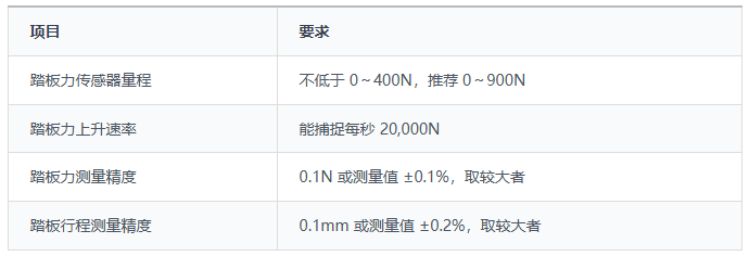
Testing includes 8 categories, ranging from 0.4g and 0.7g ramp application and release to constant travel, static release, different rates, lock-up or anti-lock brake intervention, free return, and finally rapid impact pressing, requiring pedal force to reach 120 N within 0.05 seconds.
Most test conditions involve the vehicle entering the test zone at approximately 100 km/h, slowing to about 97 km/h before pressing begins, with each condition repeated 5 times.
Processing the data yields nearly 30 metrics, such as preload force, free play, travel and pedal force at 0.4g, stiffness between 0.3g and 0.6g, hysteresis, and return time. The specification also includes an ergonomic dimension table for measuring pedal height differences, lateral spacing, and tread angle.
Additionally, there are physical vehicle tests corresponding to the strength loading (R-03) mentioned above.
04 Samples Must Represent Mass Production
Another critical and often overlooked issue in verification is whether the tested samples truly represent future mass production status.
At the time, only the pedal bracket was produced locally in China, while other brake components like calipers and wheel hubs remained European parts, so only one configuration was tested. During vehicle trial production, all localized components needed to be fitted, requiring retesting for both brake sizes.
—Project A Verification Record (Paraphrased)
In essence, changing components or suppliers means old test conclusions cannot be directly applied.
Multiple verification methods may exist for the same requirement, but whether conclusions are accepted also depends on sample and test condition compatibility.
05 Release Requires Sign-off: Authorized Personnel Sign Based on Evidence
Design and verification are complete, but the component still cannot be installed on the vehicle without passing milestone reviews.
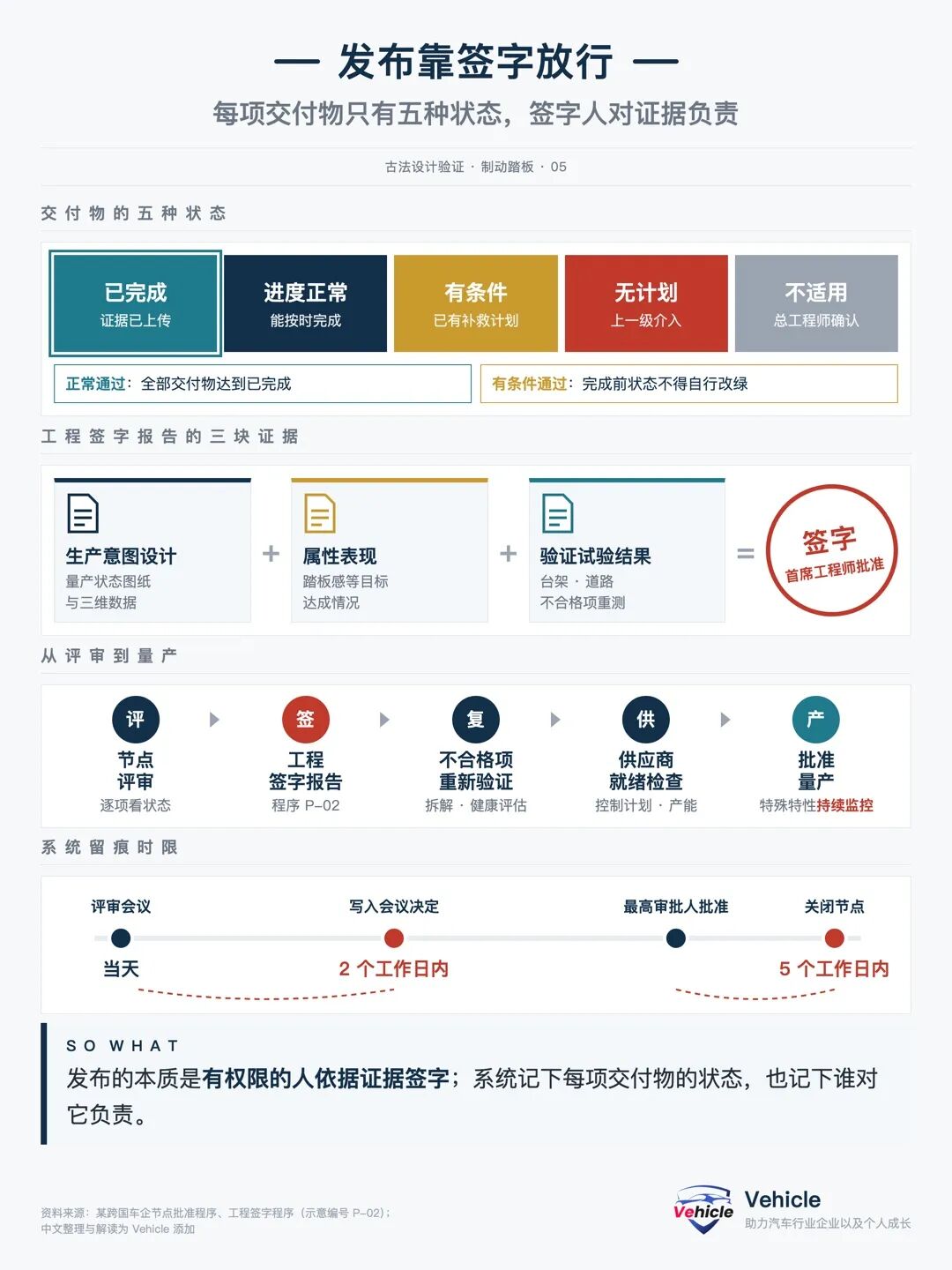
The milestone approval procedure stipulates that each deliverable can only be in one of five states: Completed, On Schedule, Conditional, No Plan, or Not Applicable.
The project is considered normally approved only when all deliverables are marked 'Completed.' Conditional approval may be applied if a remedial plan is approved, but the status cannot be changed to 'Completed' until actual completion.
All evidence must be uploaded to the project deliverable record system. Review decisions are documented within 2 working days after the review, and the milestone is closed within 5 working days after approval by the highest authority.
01 Engineering Sign-off Report
At the technical development completion milestone, the engineering department must issue a sign-off report according to internal procedure P-02, summarizing three aspects: production intent design, attribute performance, and verification test results.
Non-conformities require retesting, durability tests must be followed by teardown analysis, and the health status of critical quality characteristics is jointly assessed by attribute engineers and component engineers, all ultimately approved by the chief engineer for that function.
02 Suppliers Must Also Be Prepared
Purchased components undergo supplier-side Advanced Product Quality Planning and Production Part Approval Process, checking process development, tooling, process failure analysis, control plans, measurement systems, and capacity at each milestone.
Special characteristics defined during the design phase, such as critical hole diameters, weld quality, and material properties, are included in the supplier's control plans and continuously monitored on the production line.
I believe the most valuable lesson from the release process is that every conclusion can be traced back to a signatory.
06 Problems Trace Back to Design: Experience Is Documented in Tables to Be Passed Down
Even after mass production, issues may arise from vehicle verification, quality tracking, and after-sales service.
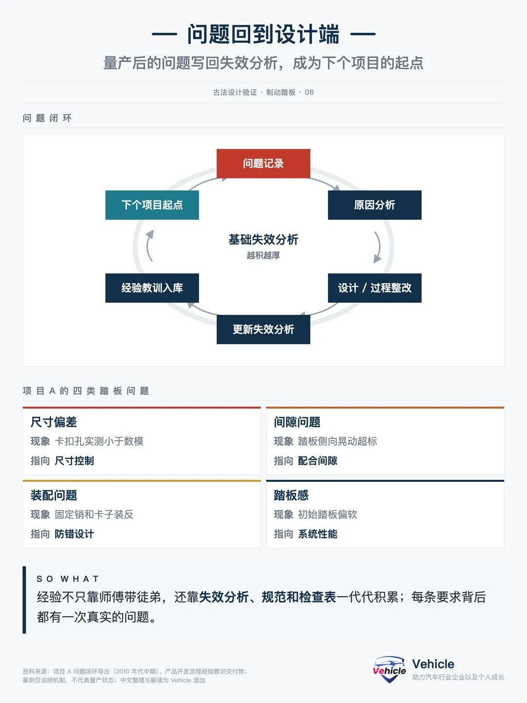
Project A's issue closure records include several brake pedal-related entries:
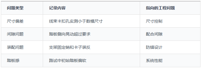
After processing, the conclusions should be written back into the Design Failure Analysis, Process Failure Analysis, or Control Plan.
The process specifically includes a “Lessons Learned” deliverable in D2, where issues uncovered in D0 and D1 are recorded into the system. Domain experts then determine whether to include them in the closed loop. For the next project’s failure analysis, input will be taken from here.
Why can basic failure analysis continuously accumulate and grow? It relies on this approach.
Behind every seemingly verbose requirement, there often lies a problem that has already occurred.
07 Final Note: The Old-Fashioned Way is Slow, but Every Step is Documented
After running a brake pedal through this process, my biggest impression is that it’s slow, but very reliable.
Requirements, methods, evidence, and signatories—every step is traceable. This approach is called the “old-fashioned way,” perhaps because it seems cumbersome, but the problems it addresses persist.
Of course, the process itself cannot replace human judgment. Decisions on which requirements to tighten, whether prototype conditions are adequate, or when to halt operations still rely on experienced engineers or the company’s accumulated database.
Finally, remember three key phrases:
1. Requirements precede drawings; methods precede testing.
2. Prototypes must represent mass production for conclusions to be valid.
3. Every conclusion must have a traceable signatory.
When examining any component, ask these four questions:
Four Questions to Assess the Robustness of a Component’s Development
1. What requirements must it meet? Are they from regulations, corporate standards, competitiveness, or component specifications?
2. What methods are used to verify each requirement? Digital modeling, bench testing, road testing, or supplier testing?
3. Do the prototypes used for verification represent mass-production conditions? Have components or suppliers changed?
4. Who ultimately approves mass production, and based on what evidence?
That’s all for today’s sharing. If you found it useful, please like, share, and tap “Seen.” Feel free to leave your thoughts in the comments section.
*Reproduction or excerpting without permission is strictly prohibited-
-
![]()
Manus Caught Between Tech Giants
-
![]()
Starting at 329,800 Yuan! BAIC Unveils New Car: Official Launch on September 28 with an Impressive 1,456 km Range!
-
![]()
Starting at 80,800 Yuan! Volkswagen Unveils New Car Model: Official Release in October, with Top Variant Priced at Only 99,800 Yuan
-
![]()
Design Verification of Auto Parts Using Traditional Methods: How Traditional Automakers Develop, Verify, and Release a 'Brake Pedal'
-
![]()
Defying Expectations! Xiaomi Pengcheng's Locked-In Orders Soar During National Day, Alongside HiCar Smart Travel's Order Surge Over the Holiday
-
![]()
Capital Sets Sights on New Model Pathway: Matrix Partners, Shunwei, and Legend Capital Jointly Invest in DiffuSpace
-
AI: Pioneering New Horizons for Smartphones
-
![]()
China Successfully Orbits 27 Satellites for Its Internet Constellation: Long March 12’s 671st Mission